· Edition #21

The Busbar

Rod Collins puts a number on the thing nobody sizes for — the BMS chip that runs your battery dies at 85V, and a failed MPPT hands it the full open-circuit voltage of your array.

Your MPPT fails shorted, your array's 141V goes straight to a BMS rated 85V — and nobody's standard covers it

Marine How To published a failure analysis on 18 September built around a 12V LFP pack that split its own steel case open after an MPPT failed. The chain is specific: MOSFETs almost always fail drain-to-source, which turns the controller into a wire; the analog front end that runs the BMS is typically a chip with an 85V absolute maximum; the BMS output FETs are often rated 60V. Rod Collins says ABYC has not addressed it.

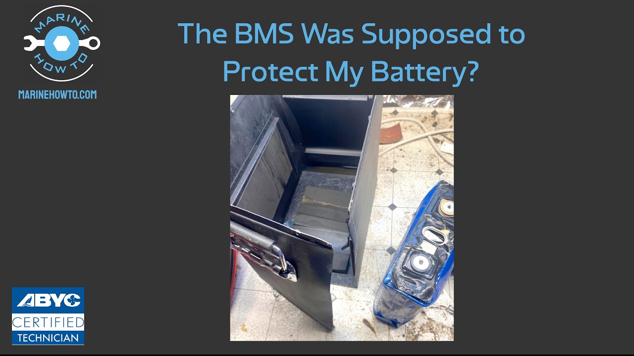
Rod CollinsMarine How To, the same bench that published the 17-year-old LFP bank we led with in June — posted a piece on 18 September that is less a product story than a sizing rule nobody currently applies. It starts with a photograph of a 12V lithium iron phosphate pack from an RV, its metal case split wide open by cells that swelled under overcharge. No fire: the cells vented white smoke and blew their vent discs, the labels melted, and that was the extent of it. Collins is blunt about why that matters — "if these had been solid state marine batteries, it would be game over."

The chain of events is the useful part, because every link is ordinary. An MPPT charge controller is, in most marine and mobile installations, a buck converter: PV-side switching MOSFETs chop the array voltage down to battery voltage. When a MOSFET fails, it overwhelmingly fails drain-to-source — a short. "Basically you're just taking the MOSFET out and replacing it with a piece of wire." Open-circuit failures happen, but they are the rare case. So the failure mode you should design against is not the controller going dark. It is the controller becoming a straight-through connection from array to battery.

What arrives at the battery then is not the array's operating voltage but its open-circuit voltage, VOC. Collins shows a real catamaran-class design sized around 116V operating, with a VOC of 141.8V, feeding a 12V LFP bank. And VOC rises as temperature falls: a 200W panel he measures at 37.44V VOC at standard conditions goes to 43.23V at −30°F, the ASHRAE design temperature for his part of Maine. Two of those in series is 86.46V — for a boat stored on the hard over winter with the solar left running.

86.46V matters because of a number almost nobody publishes. The chip that runs a BMS is its analog front end — it watches cell voltages and temperatures and drives the charge and discharge MOSFET banks. Collins holds up a Texas Instruments BQ76942 and reads its absolute maximum of 85V off the datasheet. Most AFEs sit around there. Exceed it and the AFE stops being able to turn the charge FETs off, which is the precise moment the BMS stops being a protection device. And the FETs themselves are frequently 60V-rated parts, because 80V parts cost more.

This is not a story about cheap controllers. The failed unit in the photographs is a Victron, and Collins says so plainly — "it's not just, you know, cheap Furion controllers." Rare, yes. But the mitigation is nearly free: one controller per panel keeps array voltage under 60V, and Collins notes that work he was involved in with Nigel Calder and Bruce Schwab found per-panel controllers outperform series strings on boats anyway, because of shading. The reason to know the number is that nothing in the standards will tell you it.

Four generations of JK BMS talk to each other fine — but a recovered battery tells the GX it's clear while still holding the limit at zero

Off-Grid Garage stacked V14, V15, V19 and the new V22 in one bank on a Victron system. Mixing generations works, and any generation can be master. The finding worth acting on is a recovery bug: after a low-voltage trip clears, the BMS reports the alarm cleared to VRM while still requesting 0A until actual charge current flows.

Following the V22 balancer result that led last week's edition, Andy at Off-Grid Garage published a second V22 test on 16 September, this time on communications rather than balancing. He built a five-battery stack spanning every JK Inverter-BMS generation — a V14 (firmware 14.28), two V15 (15.41), a V19 (19.31B) and the V22 (22.3) — totalling 1,278Ah, with CAN into a Victron GX.

The headline answer is undramatic and useful: they interoperate. Charge and discharge limits aggregate correctly across mixed generations, and it does not matter which generation is master — he ran the V22 as master, then made the eight-year-older V14 master with the V22 as a slave, and both worked. Addressing is unchanged: master on DIP 000000, unique addresses for each slave.

Two details are worth carrying away. JK requests 80A from the inverter when the BMS is set to 100A charge — a deliberate 20% margin so spikes don't trip the protection — and a 15% margin on discharge. And there is a genuine reporting bug. When a cell-undervoltage trip clears, the BMS holds a lock until real charge current flows, which is sensible; but it simultaneously signals alarm cleared to VRM while still requesting 0A. Andy initially read it as a V19 firmware fault, then reproduced it on the V14. He says he has raised it with JK.

Victron adds a letter to the Compatibility ID — 2617_A and 2617_B can no longer be paralleled

A label change announced 14 September that will bite on warranty replacements. Units paralleled on the same phase must now match the full Comp ID including the new letter suffix, not just the number.

Victron announced on 14 September that inverter/chargers now carry an extended Compatibility ID on the product label. The format gains a letter — Victron's own example is 2617_B — and the rule is that every unit operating in parallel within the same phase must have an identical Comp ID including that letter. A 2617_A does not parallel with a 2617_B.

This is a small notice with a specific sharp edge, and Victron names both cases itself: RMA replacements and expanding an existing parallel system. Both are situations where an installer reasonably assumes that ordering the same model number gets them a compatible unit. It no longer does. Victron's instruction is to check the full Comp ID before installing or combining units, and to work through the distributor to confirm matching IDs.

One thing we will not assert. Community discussion attributes the incompatibility to a transition to a new generation of transformer, and that is a plausible reading — but Victron's own notice does not state a technical reason, so we are not reporting one. What Victron does say is that a technical note for distributors carries the handling detail.

REDARC's REDLAB Icon Slim gets a 100Ah pack down to 62mm — and it costs more and weighs more than the fat one

Announced 15 September in 100Ah and 200Ah. The 100Ah is 62mm thick against 168mm for the standard Icon, for A$1,599 against A$1,499 — and 16kg against 12kg. You are buying a shape, and REDARC is charging for it.

REDARC added Icon Slim variants to its REDLAB lithium range on 15 September, aimed at under-seat, under-floor and canopy installs. The Icon Slim 100 (LBATS12100) is 525 × 62 × 300mm and 16kg at A$1,599; the Icon Slim 200 (LBATS12200) is 610 × 83 × 470mm and 34kg at A$2,949. REDARC states over 6,000 cycles, charge and discharge to −20°C via built-in heating pads, RedVision app monitoring and an integrated LED state-of-charge gauge.

The comparison REDARC does not make is with its own standard Icon. The Icon 100 (LBATN12100) is 308 × 168 × 211mm, 12kg, A$1,499, IP67, three-year warranty. So the slim version is 4kg heavier and A$100 dearer for the same 100Ah — a packaging premium, which is a defensible thing to sell and an odd thing to leave unstated. The Icon Slim range page does not publish an IP rating or a BMS current rating; the announcement page claims a five-year warranty against the three years listed for the standard Icon. We could not reconcile those two figures from REDARC's own pages and have flagged it.

Prices are REDARC's Australian list, read on 20 September. No US or European pricing has been published.

A circumnavigator runs 1,500W of panels into 880W of controller — and starts the engine twice

Victron's case study on Alec Hughes' 51ft sloop Manu is a useful counterexample to this week's Lead: 1,500W of solar split across two BlueSolar MPPT 75/15s, which caps array voltage well under any BMS limit. It is also over-panelled by roughly 70%, deliberately.

Victron published a case study on 15 September on Alec Hughes' 51-foot sloop Manu, circumnavigating since April 2025. The system: about 1,000W of flexible panels plus a 500W rigid panel on stern davits, two BlueSolar MPPT 75/15 controllers, two 25.6V 150Ah lithium batteries, a Yanmar 120A alternator, two Orion-Tr Smart 12/24-10A chargers protecting that alternator, a separate Orion-Tr 24/24-12A isolated converter feeding a dedicated battery for the 900W windlass, and a Cerbo GX MK2 with a GX Touch 50. Hughes reports starting the engine twice on the most recent circumnavigation.

Two observations Victron's write-up does not make. First, the arithmetic: a 75/15 is rated 440W of nominal PV at 24V, so two of them is roughly 880W of controller against about 1,500W of panel — around 70% over-panelled. On a boat that is a reasonable choice rather than an error, because flexible panels laid on a deck and coachroof are shaded, angled wrong, or both for most of the day, and clipping at noon costs less than the panels you'd otherwise never fill. It does mean the rated figure and the harvest are not the same conversation.

Second, and relevant to this week's Lead: the 75/15 tops out at 75V of PV input, and splitting 1,500W across two small controllers keeps each string's open-circuit voltage low by construction. Whether by design or by accident, that is the architecture Rod Collins spends the Lead arguing for.

The Background · Trend Piece

Every battery tells you it does 4P4S. Almost none tell you what voltage the FETs are rated to

The Lead is a failure analysis. This is the part that outlasts it: the number you need in order to size an array safely is, for most batteries on the market, not published anywhere.

Here is the arithmetic a careful builder would want to do. Take the maximum open-circuit voltage your array can present at your coldest design temperature. Compare it against the highest voltage your BMS can survive if the controller between them fails shorted. Keep the first number below the second. That is the whole rule, and it is not a hard calculation — the VOC side is on every panel datasheet, with the temperature coefficient alongside it.

The other side of the inequality is missing

Battery manufacturers publish a great deal: capacity, cycle life, BMS continuous and peak current, dimensions, weight, operating temperature, warranty, a list of certifications. What they publish about the BMS's voltage withstand is, almost universally, one derived figure — "4P4S," meaning four in parallel and four in series.

Collins' point is that 4P4S is a specification of intent, not of margin. Four 12V batteries in series, charged at 3.65V per cell across sixteen cells, is 58.4V. If the pack's MOSFETs are 60V parts — and he pulled one, an RU7088R, out of a 4P4S-rated battery on his own bench — then the manufacturer has published a configuration that runs the FETs at 97% of their absolute rating in normal service. Engineering practice would put the working point nearer 80%. He is explicit about the economics: 80V FETs cost more, so a lot of companies use the cheapest ones they can get, and most do not disclose which.

So the working assumption he lands on is a floor, not a fact: if a battery advertises 4P4S and says nothing else, assume 60V is the most its BMS will take. That is a reasonable default and an indictment of the datasheets that make it necessary. Collins notes a battery on his bench awaiting review that does use 80V FETs with a 300A BMS — we have not independently confirmed the product and are not naming it here on the strength of a passing mention.

Why the standards don't close the gap

ABYC E-13 governs lithium installations on boats and is specific about a great deal — BMS presence, overcurrent protection, charging, grounding, thermal runaway. What Collins says it does not address is this interaction: the voltage a failed charge controller can deliver into the battery's own protection electronics. "The ABYC hasn't considered it and most organizations have not even thought about it."

That is worth stating precisely, because it is not a failure of the standard so much as a seam between two of them. Array design is sized against the controller's maximum input voltage, which is printed prominently on every MPPT and which installers respect. Battery protection is specified against cell limits. The failed-controller case falls between: it is an array-side fault that lands on a battery-side component, and neither side's spec sheet is written to be read against the other's.

The practical shape of this

Three things follow, none of which require waiting for a standards revision.

One: array VOC is a number you can compute today, at your own cold-weather design temperature rather than at standard test conditions — and the gap between the two is large, 37.44V to 43.23V on the panel Collins measured. Boats stored on the hard with the solar left live all winter are the exposed case.

Two: one controller per panel is the cheap structural fix, and on a boat it was already the better-performing one for shading reasons. Small controllers are not proportionally more expensive than one large one.

Three: if a high-voltage array is already installed and rewiring it is not on the table, a high-voltage cutout between controller and battery is a bolt-on. Sterling Power's HVDC12 is the device Collins found while preparing the piece — and he says on camera that he has asked Sterling what maximum input voltage it will actually protect against and had not received an answer at the time of publication. That is the right question, and until it is answered the device's headline rating is not the same thing as a guarantee against a 141V array dump.

The disclosure gap is the durable problem. A buyer cannot currently make an informed choice between a 60V-FET battery and an 80V-FET battery, because the specification that separates them is not on the page. Until it is, the conservative floor is the only honest input to the calculation.

Community Pulse

What the forums are talking about this week

An accidental illustration of the Lead turned up on r/vandwellers on 17 September. A builder posted a hand-drawn wiring diagram for review before committing: two 200W Rich Solar panels, a 280Ah EcoWorthy LFP bank, a Victron 100/30 MPPT, a 30A solar disconnect, 10AWG from panels to controller and controller to battery, 6AWG from battery to a 30A breaker feeding the fuse box. The diagram gives a parts list but not a topology, so we cannot tell from it whether those two panels are wired in series or parallel — which, on the week's evidence, is the question. Parallel puts the array around 37V and the controller-failure case is uninteresting. Series puts it near 49V at standard conditions and higher in the cold: still under the 60V floor, but not nowhere near it.

The same poster asked separately about solar cable glands: whether to use the van's factory roof entry points or drill fresh holes, given that the gland will not sit flat over a factory penetration. Window-weld bedding plus lap sealant was their plan. It is the unglamorous half of a roof install and it is where the water actually gets in.

A third thread is a familiar shape — a builder wanting 7.2–10kWh of storage who has explicitly decided not to DIY the system, weighing a Pecron E3800LFP with expansion against Jackery and EcoFlow units, and worrying about output because they intend occasional EV top-ups. The all-in-one path keeps getting chosen for the reason it always is: not price, but not wanting to be the integrator.

As always, we can read opening posts but not replies from this environment — treat these as questions asked, not answers reached.

On the Bench

YouTube picks: builds, teardowns, firmware walkthroughs, and reviews

All JK-Inverter BMS Versions in parallel. Will 4 BMS-Generations still talk to each other?
Firmware Deep-dive
Off-Grid Garage · 16 September 2026
A 1,278Ah stack of V14, V15, V19 and V22 JK BMSes on one CAN bus into a Victron GX, with deliberate undervoltage and overcurrent trips to see what each generation reports. Includes the recovery-lock behaviour in News 1, diagnosed live and initially misattributed on camera.

Product Radar

New and notable components announced or launched this week

HVDC12 High Voltage Protection Device — Sterling Power Products
Safety

Two-stud inline relay that disconnects a 12V battery and system from an upstream source — solar controller, wind regulator — when voltage exceeds 16V. Rated 60A at 100VDC, red LED on trip, manual reset that only re-engages below 16V, 1mA draw, 90 × 85 × 90mm, M6 studs. Works with lead-acid or lithium. Made in England.

£57.60 Available from Sterling Power UK; no US distribution at the time of writing
Listed because Rod Collins surfaced it as the retrofit answer for an already-installed high-voltage array, not because we have tested it. Note what is unresolved: Collins says on camera he asked Sterling what maximum input voltage it will actually protect against and had no answer by publication. The 100VDC figure is the relay's rating, not a demonstrated survival limit against a 141V array. 12V only — no 24V or 48V variant exists.

Slim-format 12V LiFePO4 for under-seat, under-floor and canopy installs. Icon Slim 100 (LBATS12100): 525 × 62 × 300mm, 16kg. Icon Slim 200 (LBATS12200): 610 × 83 × 470mm, 34kg. Built-in heating pads for charge and discharge to −20°C, RedVision app monitoring, integrated LED state-of-charge gauge, 6,000+ cycles claimed.

A$1,599 (100Ah) / A$2,949 (200Ah) — REDARC Australian list, read 20 September 2026 Australia; no US or EU pricing published
The 100Ah slim is A$100 more and 4kg heavier than REDARC's own standard Icon 100 for identical capacity. That is the cost of the shape, and it is a fair trade if 62mm is what makes the install possible. REDARC does not publish an IP rating or BMS current rating for the Slim variants, and its warranty claim conflicts with the three years listed for the standard Icon.
BlueSolar MPPT 75/15 — Victron Energy
Solar

Small MPPT charge controller: 15A charge current, 75V maximum PV open-circuit input, 440W nominal PV at 24V (220W at 12V).

Not restated here — widely stocked, street pricing varies by region Long-standing product, available now
Newly relevant rather than new, and listed for one reason: it is the part that makes this week's Lead actionable. Read the caveat before the recommendation, because the protection comes from the wiring practice and not from the controller. One panel per 75/15 keeps what a failed controller could hand your BMS under the 60V working floor the Background argues for. The 75/15's own nameplate will happily accept 75V of PV, which is two 200W panels in series — 74.88V at standard conditions, and 86.46V at Rod Collins' −30°F design temperature. That is his danger example, not his safe one. Per-panel controllers were already the better answer on a shaded boat deck; Alec Hughes is circumnavigating on two of them.